
LM3914
Analog display driver for LED bar graphs and dot meters
The LM3914 is an analog integrated circuit designed by National Semiconductor in the late 1970s. It drives up to ten light emitting diodes or other displays to show signal strength, using internal comparators and a reference voltage.
- Drives up to 10 LEDs, LCDs, or VFDs
- Uses linear scaling with ten 1000 ohm resistors
- Operates on 3–25 V supply voltage
- Supports bar-graph and dot display modes
- Expandable to over 100 segments with multiple chips
What it is
The LM3914 is an integrated circuit that controls visual displays for analog signals. National Semiconductor created it in the late 1970s. The chip manages up to ten outputs, which can connect to light emitting diodes, liquid crystal displays, or vacuum fluorescent tubes. Its primary role is to translate a changing voltage into a visible scale. This makes it suitable for building simple voltmeters or level indicators. The device uses linear scaling to divide the input range into equal steps. Users can link multiple chips together to create longer scales with more than one hundred segments.
How it came about
National Semiconductor developed this circuit during the late 1970s. It was part of a broader family of display drivers that included the LM3915 and LM3916. These three chips share the same basic design but differ in how they space their output thresholds. The LM3914 was built to provide a straightforward way to visualize analog data without complex digital processing. Texas Instruments now provides documentation for the component, reflecting industry consolidation over time.
Inside the chip
Inside the chip, ten comparators monitor the input voltage against a resistor network. A stable 1.25 volt reference source sets the baseline for these comparisons. As the input signal rises, each comparator activates in sequence. The internal resistors are all 1000 ohms, creating uniform linear steps. Users can choose between two display styles. Bar graph mode lights up all LEDs up to the current level. Dot mode illuminates only the single LED corresponding to the present value. The circuit regulates output current between 2 and 30 mA to protect the displays.
How it was made
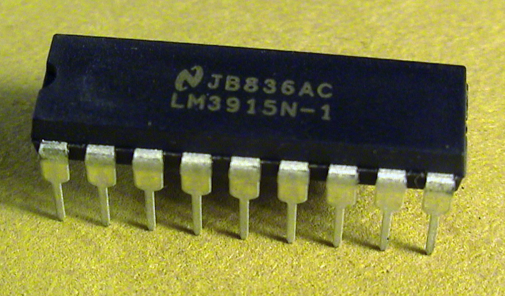
The device operates on supply voltages from 3 to 25 volts. It comes in an 18 pin dual in-line package or a surface mount leadless chip carrier. The chip relies on an internal array of ten precision resistors to set the trigger points for each output stage. This resistor ladder is the key difference between this model and its logarithmic or VU meter siblings.
Where it went
Engineers use this chip to build analog panel meters and signal strength indicators. It is common in audio equipment, test instruments, and automotive dashboards. The linear response makes it ideal for voltmeters where equal voltage changes should look equal on the display. By connecting several units in series, designers can create high resolution bars for detailed monitoring. It drives LEDs directly, removing the need for external transistors in many simple circuits.
Versions and family
The LM3915 and LM3916 are close relatives. The LM3915 uses logarithmic steps suited for audio levels, while the LM3916 follows VU meter standards. All three share the same pinout and voltage requirements. They differ only in the values of the internal resistor divider. This allows designers to swap them if they need a different response curve without changing the board layout. The LM3914 remains the choice for linear measurements.
Why it matters
This circuit simplified the creation of analog visual interfaces. Before such integrated solutions, building a ten segment driver required many discrete components. The LM3914 reduced part count and design time. It became a standard building block for hobbyists and professionals alike. Its ease of use helped popularize LED bar graphs in consumer electronics during the 1980s and 1990s.

Questions people ask about LM3914
What does the LM3914 do?
It drives up to ten LEDs or other displays to show the strength of an analog signal. It converts voltage levels into a visual bar graph or dot display using internal comparators.
How is it different from the LM3915?
The LM3914 uses linear steps for equal voltage intervals. The LM3915 uses logarithmic steps, which are better for audio signals. They have different internal resistor values but similar pinouts.
Can I connect multiple LM3914 chips together?
Yes. You can link them in series to create scales with more than 100 segments. This allows for higher resolution displays without needing a different type of controller.
Good reading and sources
The facts on this page come from the Wikipedia article "LM3914", written by its contributors and used under the CC BY-SA 4.0 licence, and from its Wikidata record (CC0). EveryChip rewrote the text in its own words, with AI assistance, and compares every page with the article to make sure no passage is copied. It may be reused under the same CC BY-SA 4.0 licence with a link back.
It may contain mistakes, and figures change over time. Nothing here is investment or buying advice. If something is wrong, tell us. Last refreshed 2026-11-14.
Like LM3914
All analog, power and mixed-signal 🇺🇸 United StatesULN2003A
Seven-channel high-voltage Darlington transistor array driverAnalog
 🇺🇸 United StatesLM358
Low-power dual operational amplifier for single-supply circuitsAnalog
 🇺🇸 United StatesICL8038
Voltage-controlled waveform generator chip by IntersilAnalog · Other
More from National Semiconductor
All of them World78xx
Family of fixed positive linear voltage regulator integrated circuitsAnalog
 🇺🇸 United StatesLM386
Low-voltage audio power amplifier integrated circuitAnalog
 🇺🇸 United StatesLM13700
Dual operational transconductance amplifier for analog audio circuitsAnalog